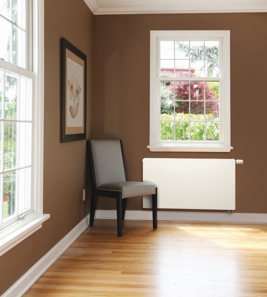

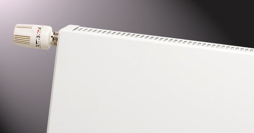
- Radiator with a smooth surface design
- Comprehensive range to suit all applications
- Enhanced user control and room comfort with use of thermostatic head
- Can be used with most thermostatic head brands
- Insert valve supplied fitted on the radiator upon request
- Robust packaging ensuring long-lasting protection during transport and on-site
Standard installation kit
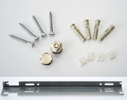 1. Comprehensive hardware pack including airvent & blind plugs, screws and screw caps
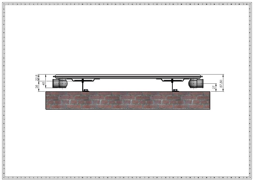
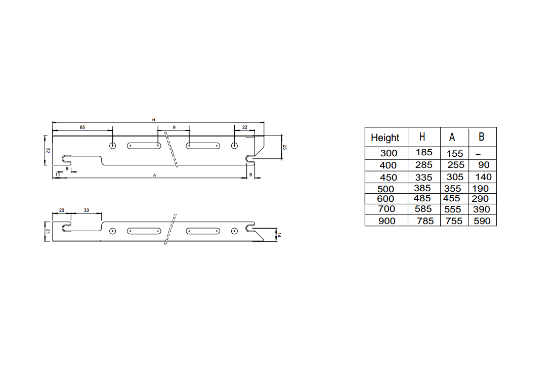
2. “L” wall brackets providing mounting flexibility (other bracket options available on request)


- Steel and Production
Termo Teknik panel radiators are produced in accordance with the internationally accepted EN 442 & BS EN ISO 9001 standards on 5 modern Swiss and Italian based prodution lines. Cold rolled steel conforming to EN 10130 is used in the production; surface treatment and painting processes take place in accordance with DIN 55900-1 standard.Steel thicknesses used in panel radiator production is:
-Panel production : 1.20 ± 0.09 mm
-Fin production : 0.45 ± 0.05 mm
-Top and side covers : 0.75 ± 0.09 mm - Fins maximizing heat output:
The fins are welded on top of 33.33mm pitched water channels to provide high heat output performance. - Every radiator is pressure tested following production:
-Radiator test pressure: Maximum 13 barr
-Radiator working pressure: Maximum 10 bar
-Maximum working temperature: 95 °C - Surface Treatment and Painting
All radiators are applied with surface treatment before they are painted. The surface treatment process includes 3 stages:
-Degreasing @ 55-65 °C
-Phosphating @ 55-65 °C & pH=4.8-5.5
-Three-step rinsing process @ various conductivity levels. - Painting
After surface traetment process, radiators go to painting as follows:
Environmentally friendly primary (dip) paint: white, water-based epoxy ester, cured at 160°C
High quality powder paint: RAL 9016, 60 gloss, epoxy polyester, cured at 180°C. Termo Teknik operates with 3 Swiss based painting cabins providing optimum energy usage depending on production output. - Accessories
All Termo Teknik radiators are provided with factory fitted top grills and side panels and they include “L”-wall hangers and an accessory bag with the following contents:
-Screws and plastic wall plugs
-Blanking plug G 1/2”
-Airvent plug G 1/2”
-Various other wall brackets, floor stands and accessories are available upon request. - Termo Teknik Logo:
Please look out for the Termo Teknik logo on the side panels as a guarantee of Termo Teknik’s high quality and assurrance. - Packaging and Labelling
Lugs welded at the back of the radiators are protected by plastic supports against damages. Sides of the panels are supported with grooved card-board protectors against possible harms from external effects. Finally, the radiators are wrapped with shrink-wrap plastic against wetness, humidity, dust.
This heavy duty packaging minimizes the risk of damage during transportation, at the construction sites and during installation. In order to prevent damages to the radiator surface and paint, it is advised that the wrapping of the radiator should be kept on until all construction work at the site is completed. - Palletizing
For maximum protection of radiators during transit and storage, Termo Teknik uses custom made pallets which conform to ISPM 15 standard. In general, there are two ways of palletizing.*Quantities shown in above drawings are illustrative only. Actual pallet loading quantities may vary depending on way of shipment and destination. - Warranty:
All Termo Teknik panel radiators are provided with 10 year warranty against defects in material or workmanship.
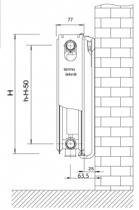
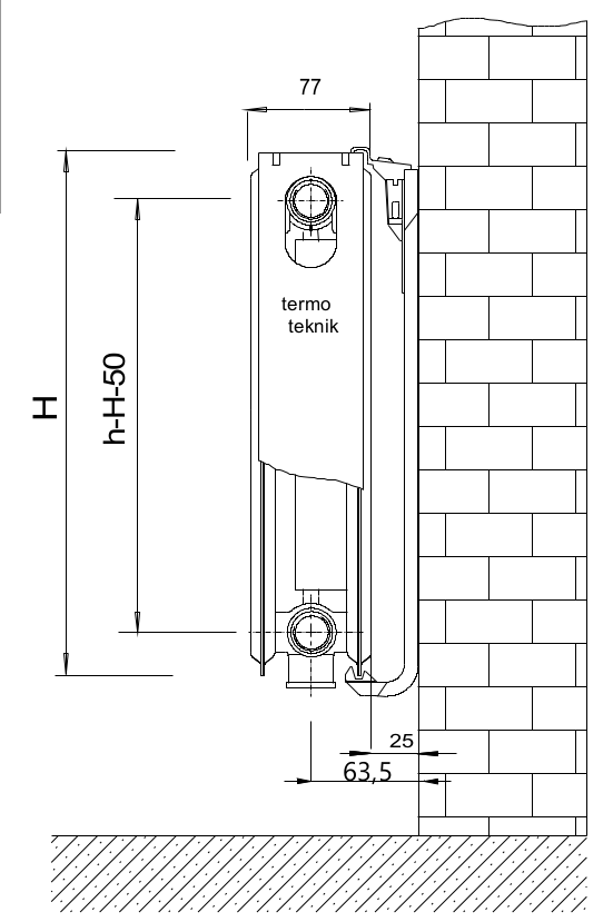
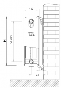
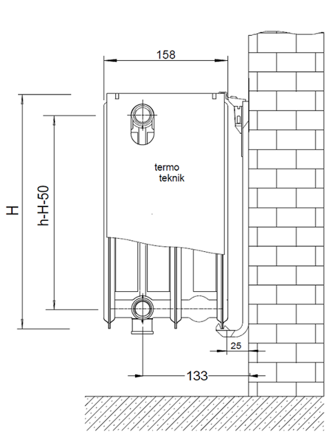
Types and dimensions
-

- TYPE 11 skies
-
- TYPE 21 skies
-
- TYPE 22 skies

-

- TYPE 33 skies left side
-

- TYPE 33 skies normal
-
- TYPE 44 skies

-

- TYPE 10
-
- TYPE 11
-
- TYPE 20
-
- TYPE 21
-
- TYPE 22
-
- TYPE 30
-
- TYPE 33
-
- TYPE 44
Heat outputs
![]() Download to use the heat output calculation table!
Download to use the heat output calculation table!
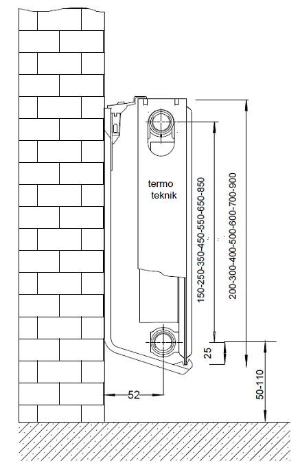
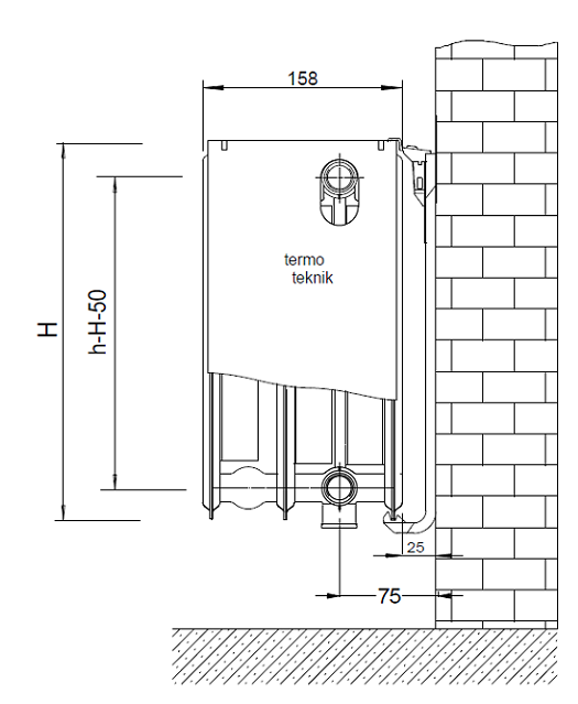
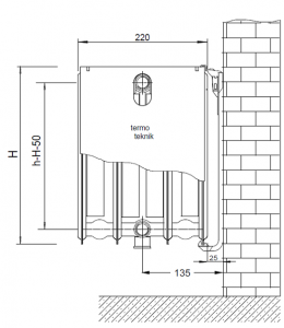
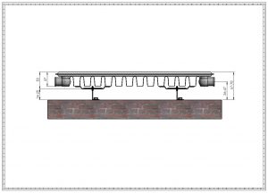
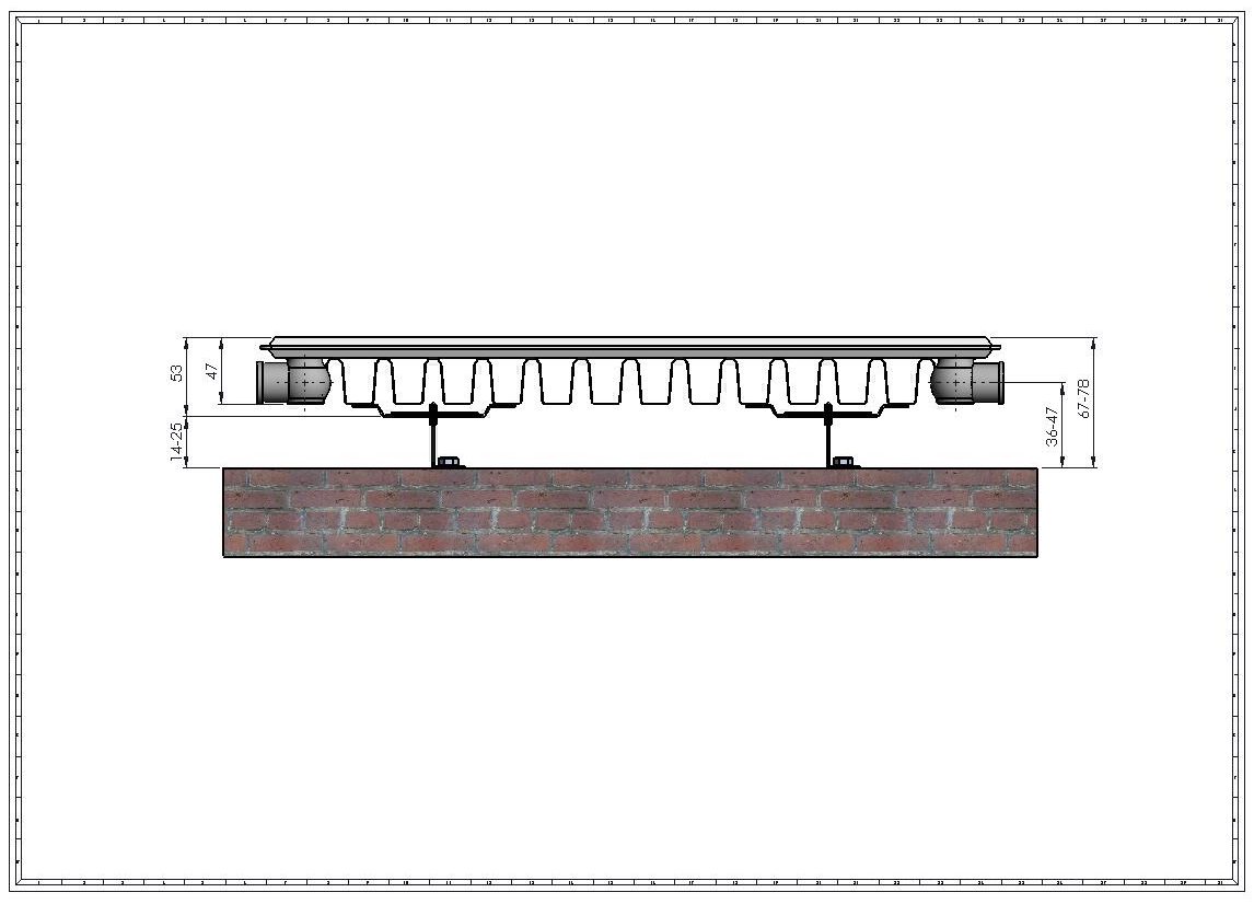
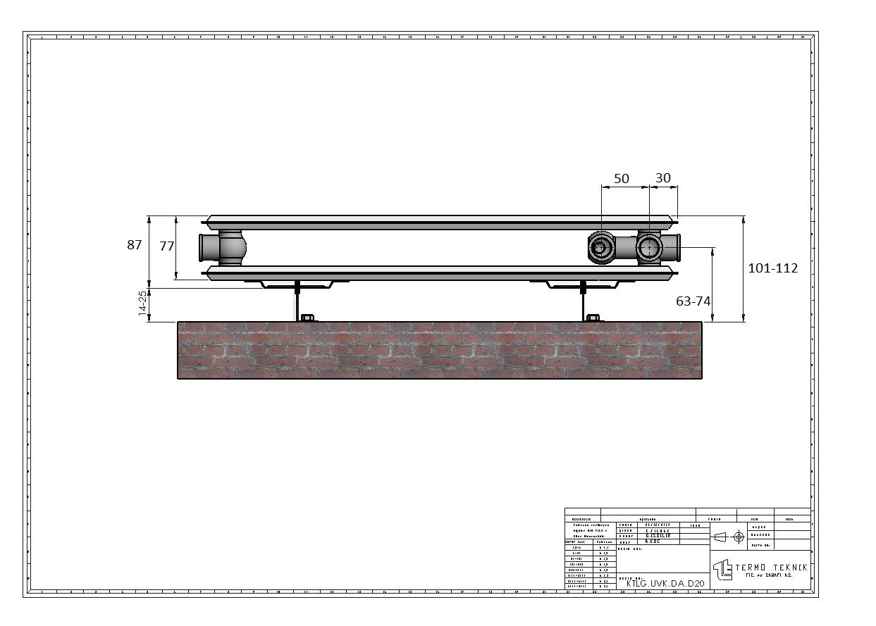
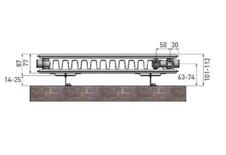
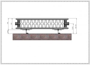
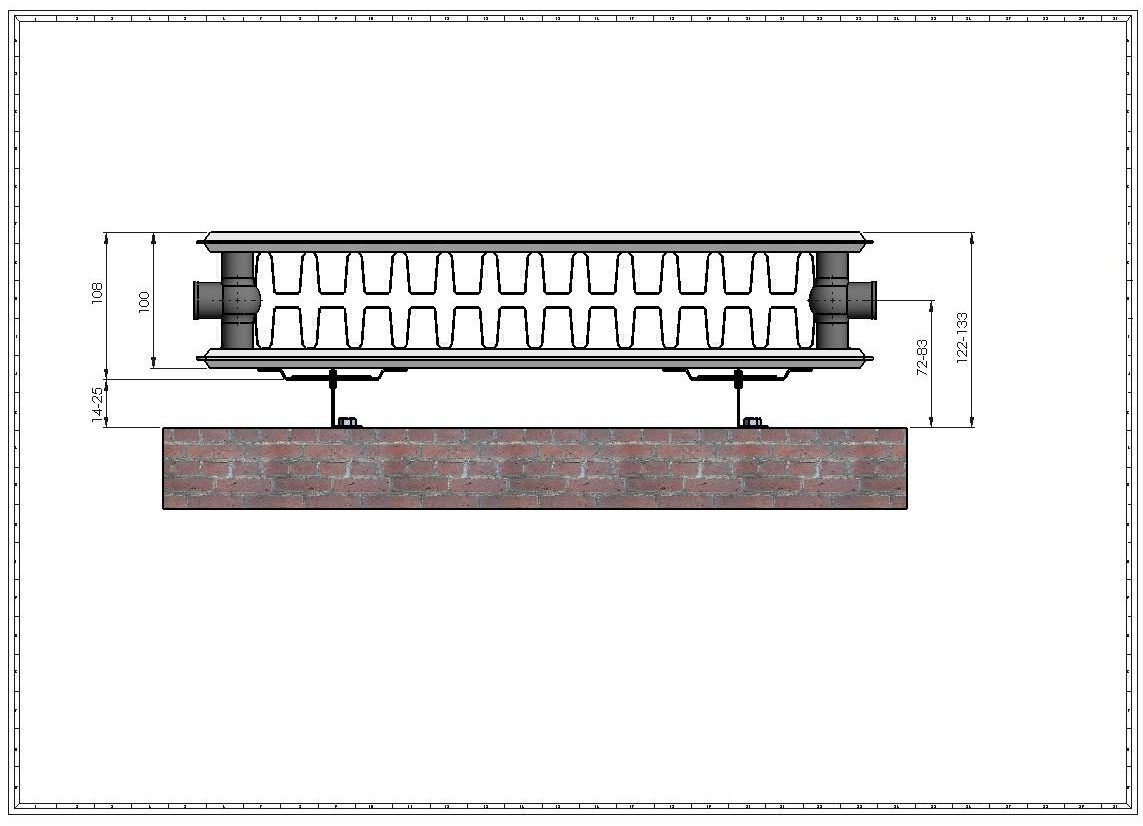
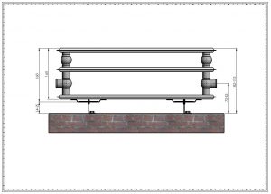
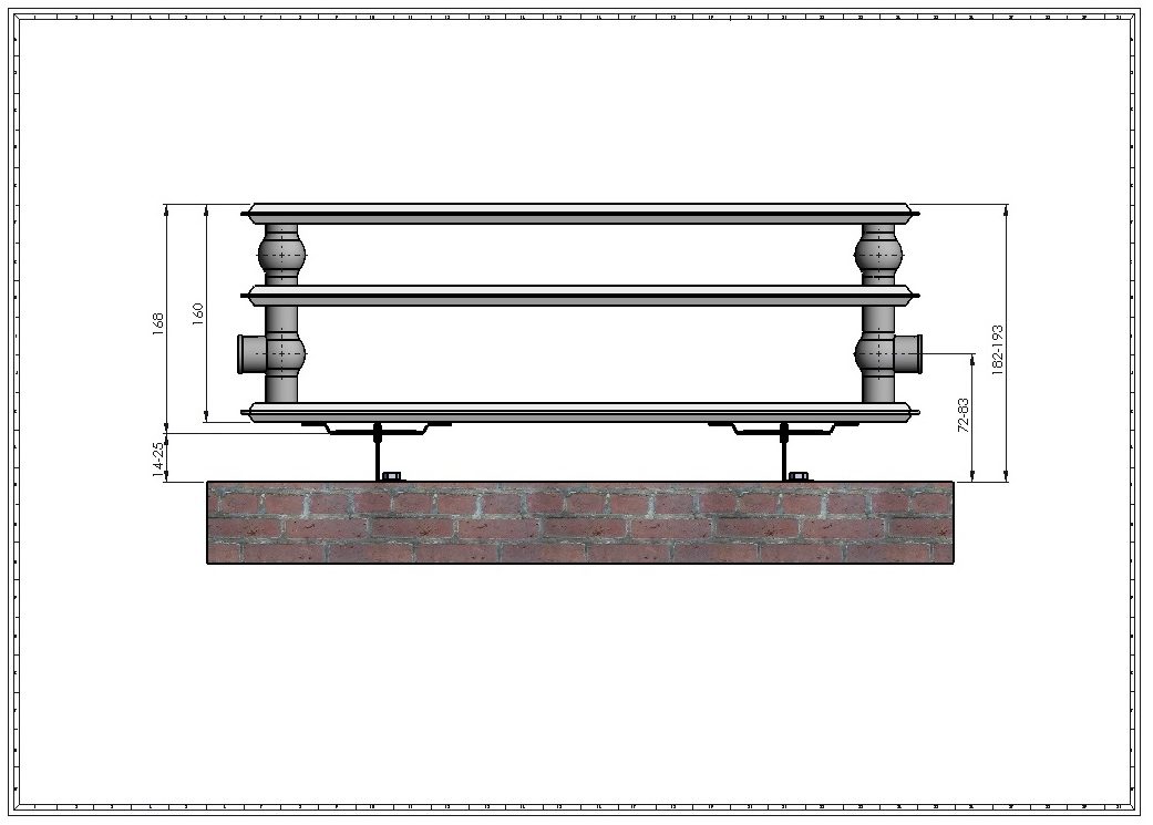
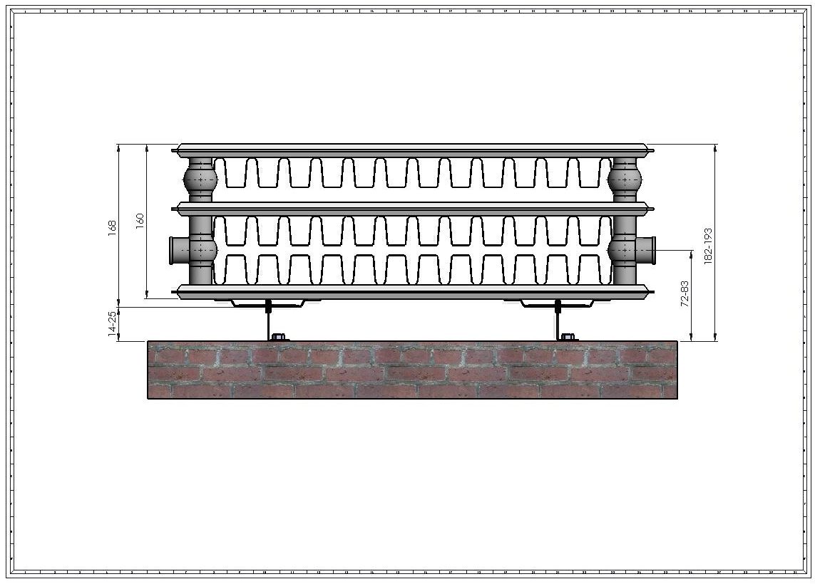
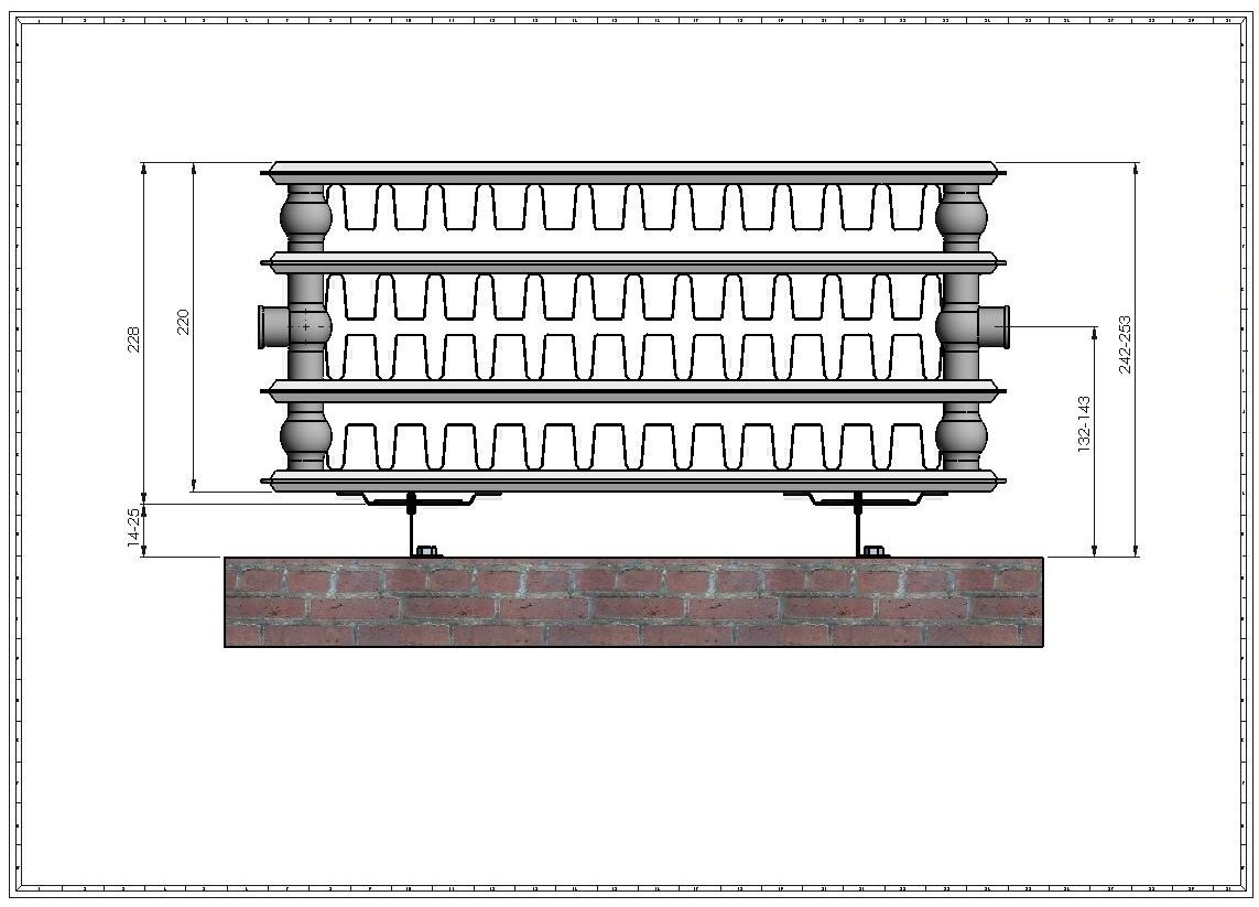
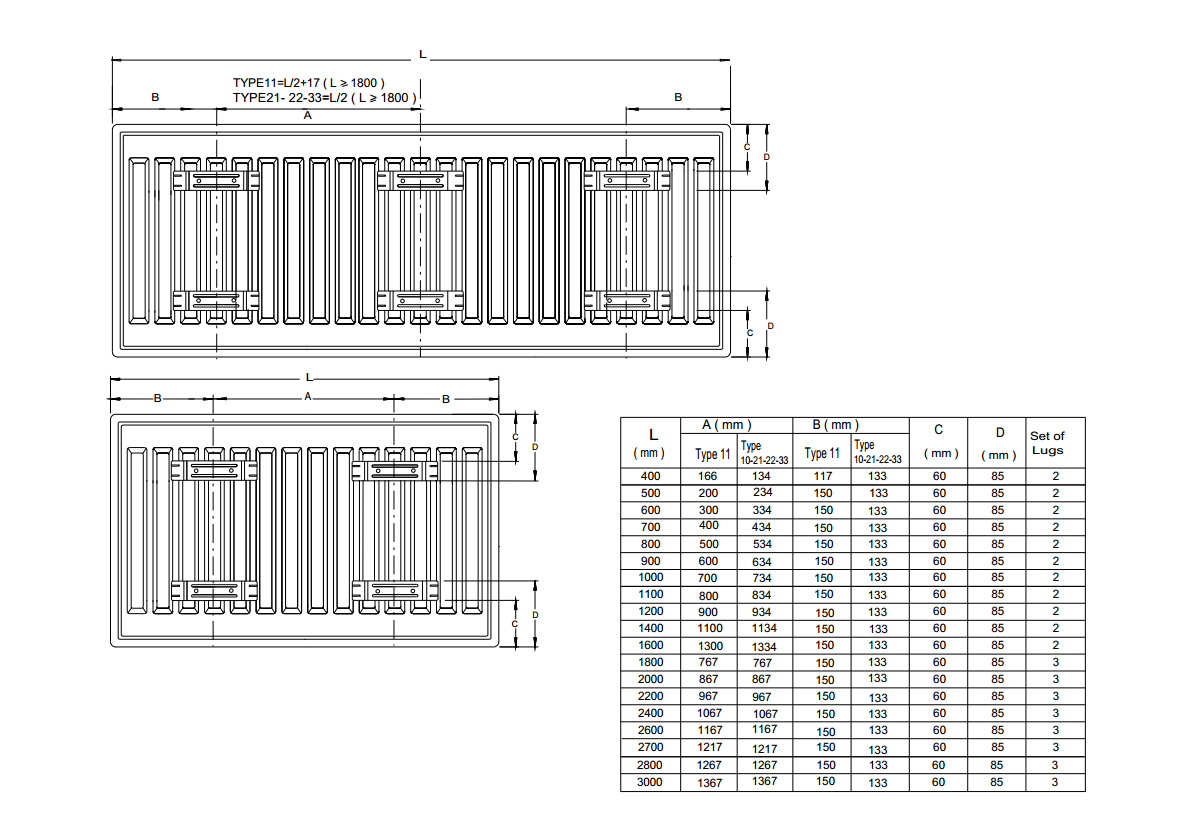
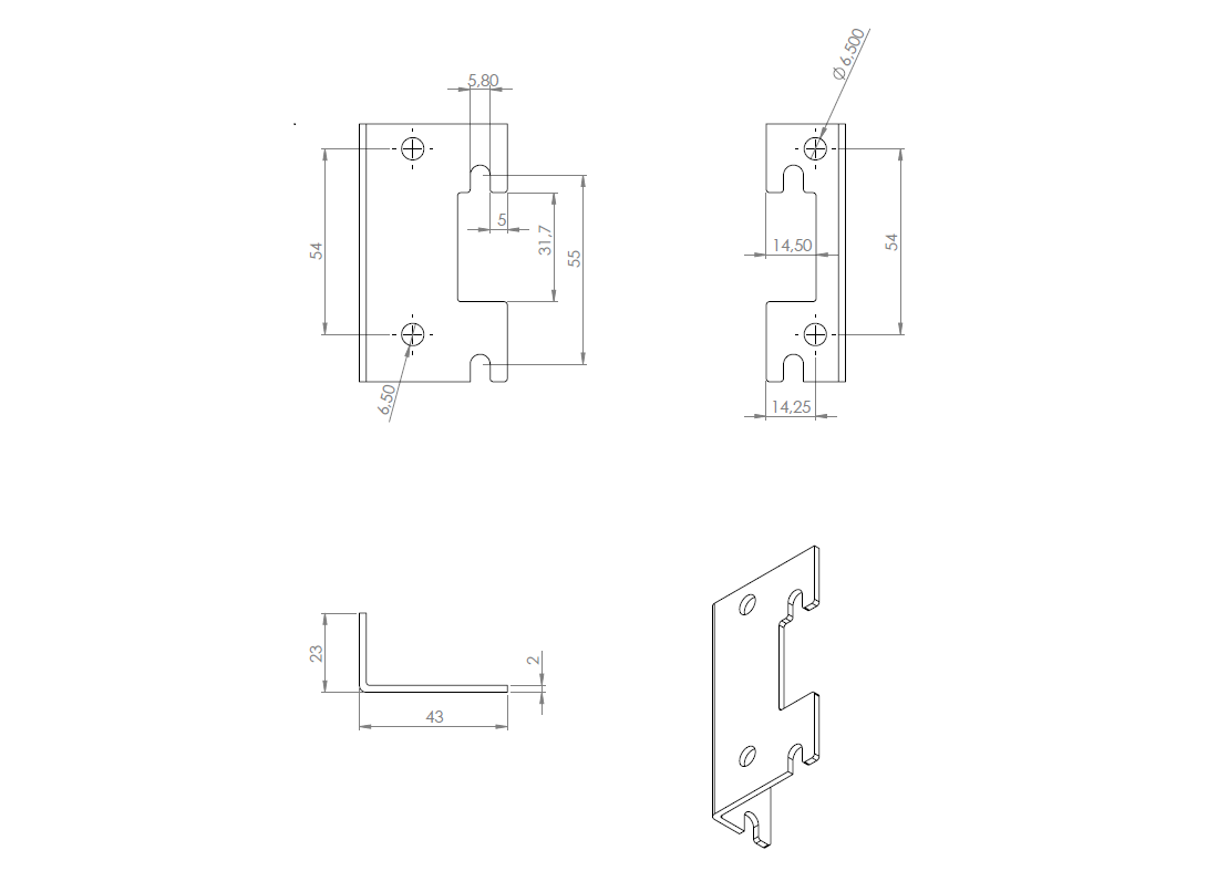
Positioning of lugs, brackets, floor stands and wall skies
View the files by clicking the download icon next to the file name:
![]() Sigarth Floor bracket MSC 120-215
Sigarth Floor bracket MSC 120-215
Connection methods
1. Top Bottom Same End Connection
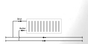 Hot water enters from the top and exits from the bottom of the same side. It is the most advised and used method, and in most cases the most energy efficient.
2. Top Bottom Opposite End Connection
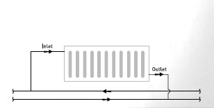 This method is generally advised for long raditors where the length of the panel radiator is 4-5 times more than the height.
Example: This method is advised for 500 mm high radiator with lengths of greater than 2250 mm (500 x 4.5 = 2250 mm).
3. Bottom Opposite End Connection
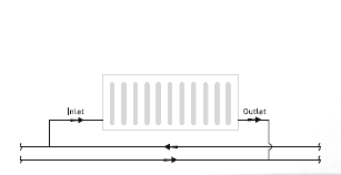 This method is not advised unless absolutely necessary. There will be an output loss of heat 10-20%, depending upon the height of the radiator. In this method, it is important that the right output radiator is chosen.
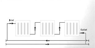
4. One pipe system
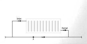 In this installation method, the length and the diameter of the by-pass pipe should be calculated accurrately to minimize pressure drop whish will reduce the heat output of the radiators. A pump may be used to control the water pressure. In this form of connection, it should be taken into consideration that every radiator will have a different average temperature.
5. Serial Connection
 This is a method used for connecting a series of radiators and is used very rarely. If it must be used, the total heat output of the series must not exceed 7000-8000 kcal/h, otherwise the capacity of the circulation pump will be exceeded. The capacities of the series should be calculated carefully because of the different average water temperature between each panel.
Installation Recommendations
Installation of a radiator requires above average DIY skills therefore we recommend that radiators are installed by a professional and qualified plumber unless there is a good reason not to go down this route.
For good practice and to reduce damage risk to the radiator, please make sure that:
- The packaging is kept on the radiator until the decoration is completed or the heating is turned on permanently. This will protect the radiator from damages that may potentially happen during decoration work
- Radiator is not dragged on the floor, but lifted properly
- There is sufficient space around the radiator for circulation of air.
You can refer to the “Impact of Installation Positions on Heat Outputs” below for more information.
- Based on the inlet and outlet positions specified in the heating project, outline the radiator position on the wall. Using the lug position data and wall bracket dimensions in this catalogue, identify and mark the wall hung brachet positions on the wall.
- Remove the brackets and hardware pack from the radiator by cutting the film and the cardoard at the bottom of the radiator where necessary.
- Fix the brackets on the wall using the screws and screw caps provided in the hardware pack. Make sure the plastic saddle clips are fixed on the brackets to prevent noise when the radiators are in use.
- Cut out the film and the cardboard over the lugs at the back of the radiator and remove the lug protectors. Mount the radiator on the brackets.
- Mount the blind plug and airvent on the radiator and connect the pipes to the radiator.
Impact of Installation Positions on Heat Outputs 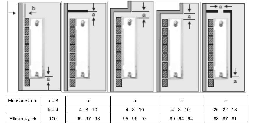
The surroundings of the radiator must be clear for it to provide the outputs stated in the catalogue. If any above fixing methods is applied for any reason, the heat output will decrease as shown in the figures.
Example:
If 600/22/1000 radiator is connected as in Figure 5 and if a= 18 cm, then the efficiency would be 0,81; Qn = 1672 watt (from the catalogue)
The real output will be
Qn = 1672 x 0,81
Qn = 1354 watt
A reflective surface (such as aluminum sheet) on the wall behind the radiator will increase the efficiency by reflecting heat back into the room. This is especially impotant if the radiator is installed in front of a glass window or a thin uninsulated wall.
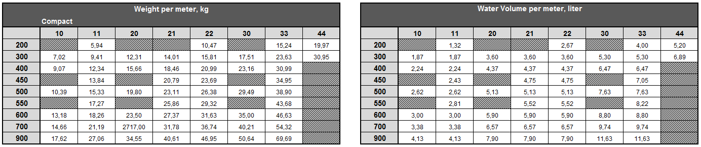
Water capacity and weight
Heat loss calculation and radiator selection
There are two main factors that will help you in specifying the right radiator:
- Desired room temperature
- The heat loss from the room.This depends on a wide range of factors such as the wall type (brick, insulated brick etc), number of exernal walls, what is above / below the room, window surface, window material etc.
The heat loss calculations can be complicated therefore we recommend that a heating engineer is consulted for precise calculation. However there is a practical method to calculate the heat loss and radiator size that is required. The heat loss from the room can be broadly calculated by measuring the space in cubic meters and then applying the following factors to the figure arrived at.
Lounges: 50
Bedrooms & Kitchens: 45
Common Areas: 40
Example:
“Heat loss = Room Volume (H x W x L) x Factor”
Room Height: 2,5 mt
Room Width: 5,0 mt
Room Length: 6,0 mt
Therefore Room Volume is: H (2,5mt) X W (5,0mt) X L (6,0mt) = 75m3
For a lounge that is 75m3 the heat loss can be calculated as follows:
75m3 x 50= 3,750 Watts (@Dt50C)
It may not be possible to choose a radiator that will exactly match the required heat therefore any radiator with the nearest output can be chosen. For large rooms two radiators may be required for better room comfort. The total output of the two radiators together needs to be equal to the required heat.
Pressure drop calculation
Pressure drop in a piping system is a result of resistance to flow. Total pressure drop is a critical issue for selecting pump size. The pressure drop of a radiator depends on water flow rate and radiator size. It is significant for bigger size radiators.
The pressure drop calculation of panel radiators, as a part of total pressure drop of the system, is given below with an example.
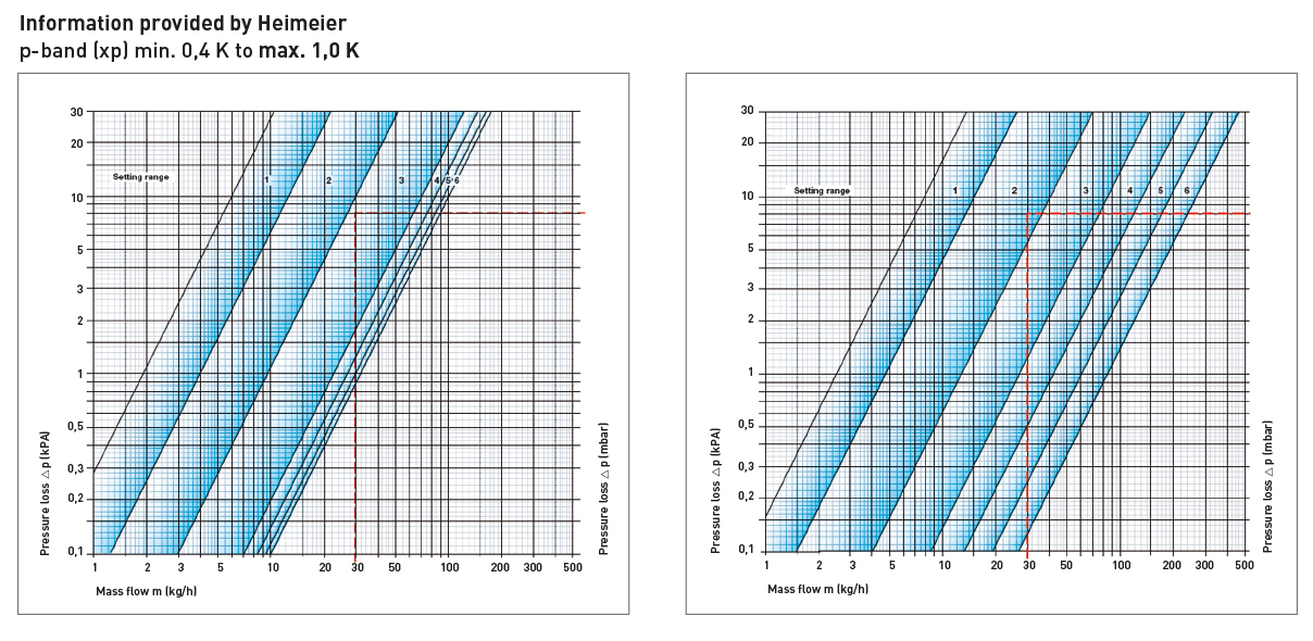
Pressure loss of a radiator can be found using the pressure drop graphs of radiators with and without valve insert (please note that for radiators with valve insert we refer in our documentation to the supplier of the valve insert Heimeier).
Pressure drop of a radiator without valve insert
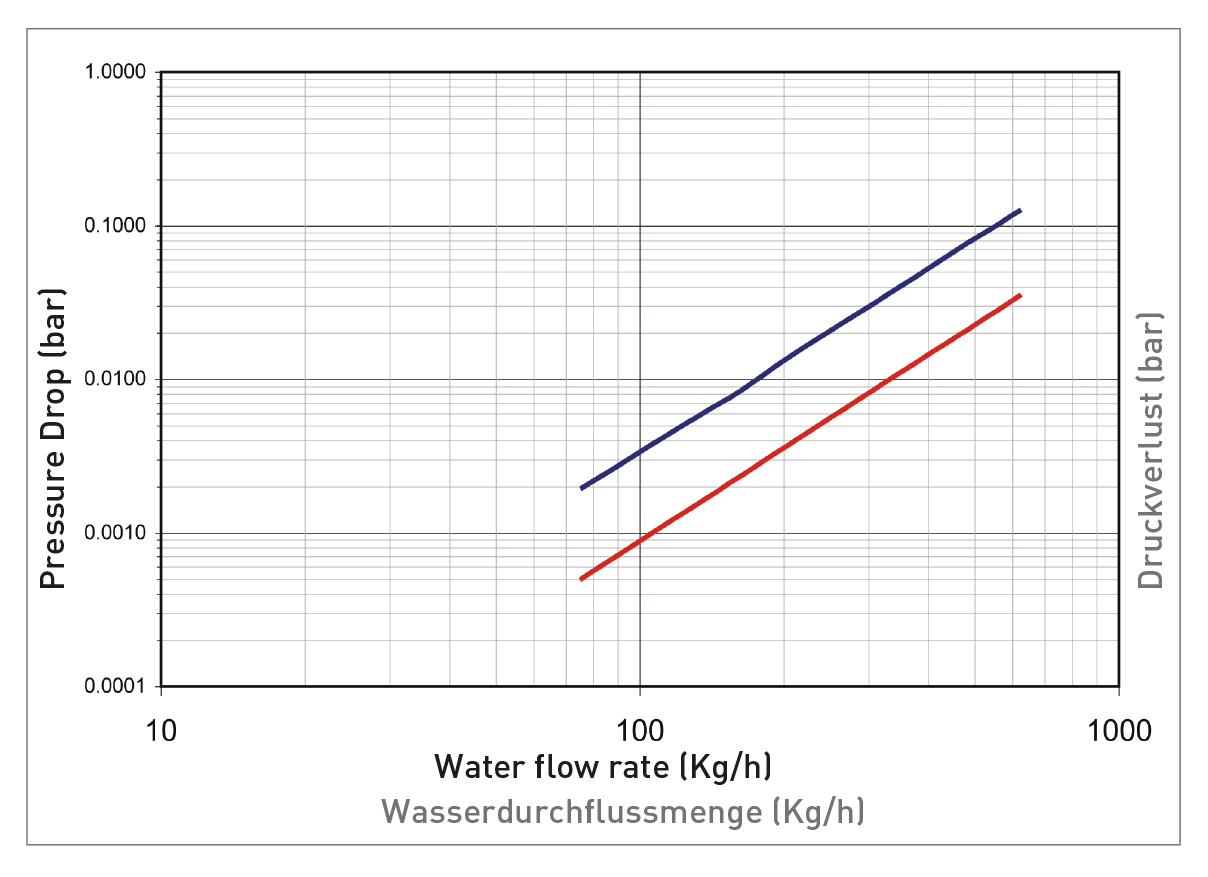 Example: What is the pressure drop on a radiator of size 600/22/1000?
Qn=1672 watt = 1441 kcal/h for a 600/22/1000 radiator @ 75/65/20 nominal temperatures
Water flow rate = Qn/(water inlet temperature-water outlet temperature)
Water flow rate = 1441 / (75-65)
Water flow rate = 144.1 kg/h
Having known water flow rate 144.1, the pressure drop is read on the y-axis of graph as 0.002 bars (using the Type 22 line).
Pressure drop chart of a radiator with insert valve
Capacities of radiators in varying water and room temperatures
The radiator heat output varies according to water and room temperature changes.
Heat outputs at temperatures other than those 75/65 °C water inlet/outet temperature and 20 °C room temperature are calculated using “F” factors enabling you to find the performance of standard radiator (75/65 °C and 20 °C) at different room and water temperatures.
The “F” factors are given in Table 2 (please see the F Factors Sheet below).
The following are two examples demosnstrating usage of “F” factors:
Example 1:
The heat output for 600/22/1000 Termolux Classic radiator at (75/65 °C and 20 °C) is Qn=1672 watts (from Table 1.A.). What will be the heat output at 70/55 °C water inlet/outlet temperatures and 18 °C room temperature?
In Termolux “F” factor table (Table 2) the first vertical column shows the incoming water temperature; the second vertical column shows the room temperature and the horizontal rows show the outgoing water temperature. When those columns are intersected, the “F” factor is found.
The “F” factor at 70/55 °C and 18 °C is 1.18. The new heat output is calculated with the formula:
Q = Qn / F
Q = 1672 / 1.18
Q = 1417 watt
Q: Required heat output
Qn: Standard heat output (at 75/65 and 20 °C)
F: Capacity factor from the table
Example 2:
“F” factor table can also be used to choose a radiator for a site (room or area) whose heat requirement has already been calculated.
Let’s assume that the calculated heat requirement for a room is Q = 1500 watt. How can we select and calculate the heat output of a standard radiator at 70/55 °C water inlet/outlet temperatures and 18 °C room temperature?
The “F” value from Table 2 (please see the F Factors Sheet below) is 1.18.
Qn = Q x F
Qn = 1500 x 1.18
Qn = 1770 watt
Then we choose from the Table 1.A (at 75/65 and 20°C) a radiator with Qn = 1770 watt.
If we straight away choose a radiator from the catalogue with a heat output of 1500 watt instead of 1770 watt, the temperature of the room would not come to the desired standard.
The above example shows how a non-standard condition can be converted to a desired standard condition.
![]() TABLE 2A. F FACTOR TABLE FOR PANEL RADIATORS
TABLE 2A. F FACTOR TABLE FOR PANEL RADIATORS
![]() TABLE 2B. F FACTOR TABLE FOR TERMOLINE AND TERMOLINE PLUS
TABLE 2B. F FACTOR TABLE FOR TERMOLINE AND TERMOLINE PLUS